MODERNIZACJA LINII KOLEJOWEJ BUKARESZT-KONSTANZA: SEKCJA 2, ODCINEK FUNDULEA – LEHLIU, OBSZAR 1 – MOST PRZY (RUMUNIA)
KLIENT
Astaldi S.p.A.
Przybliżoną wartość PRACY
€ 8,000,000
Rok budowy
2010
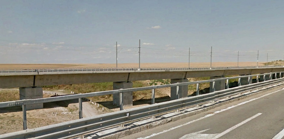
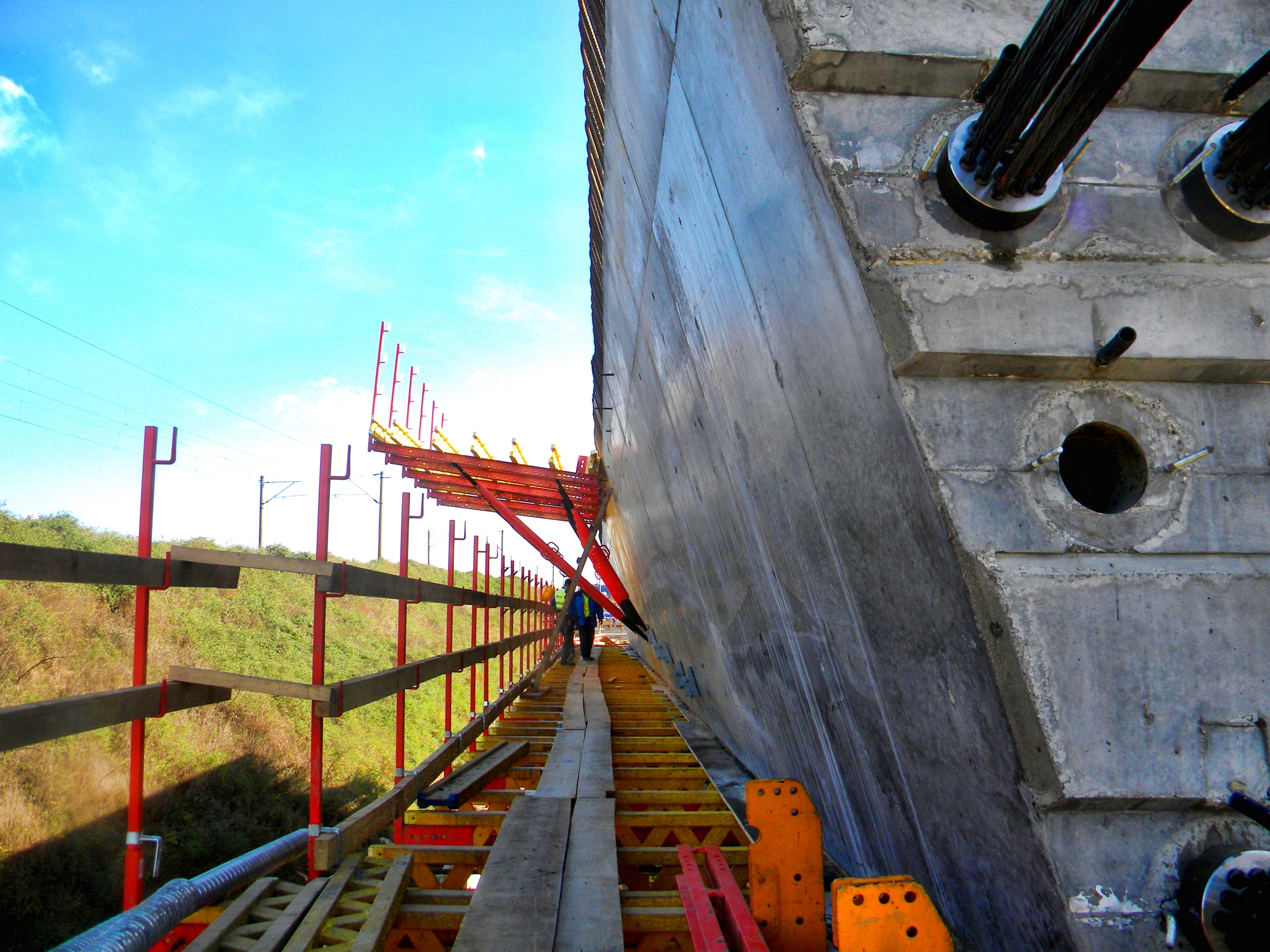
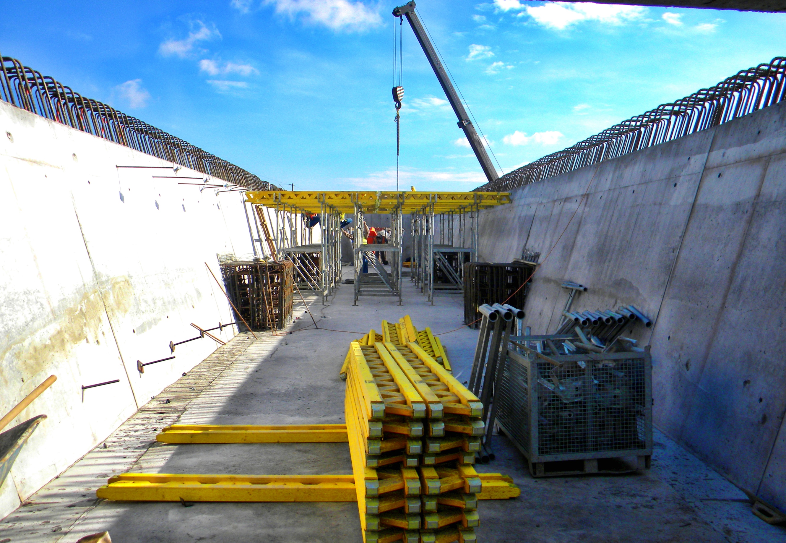
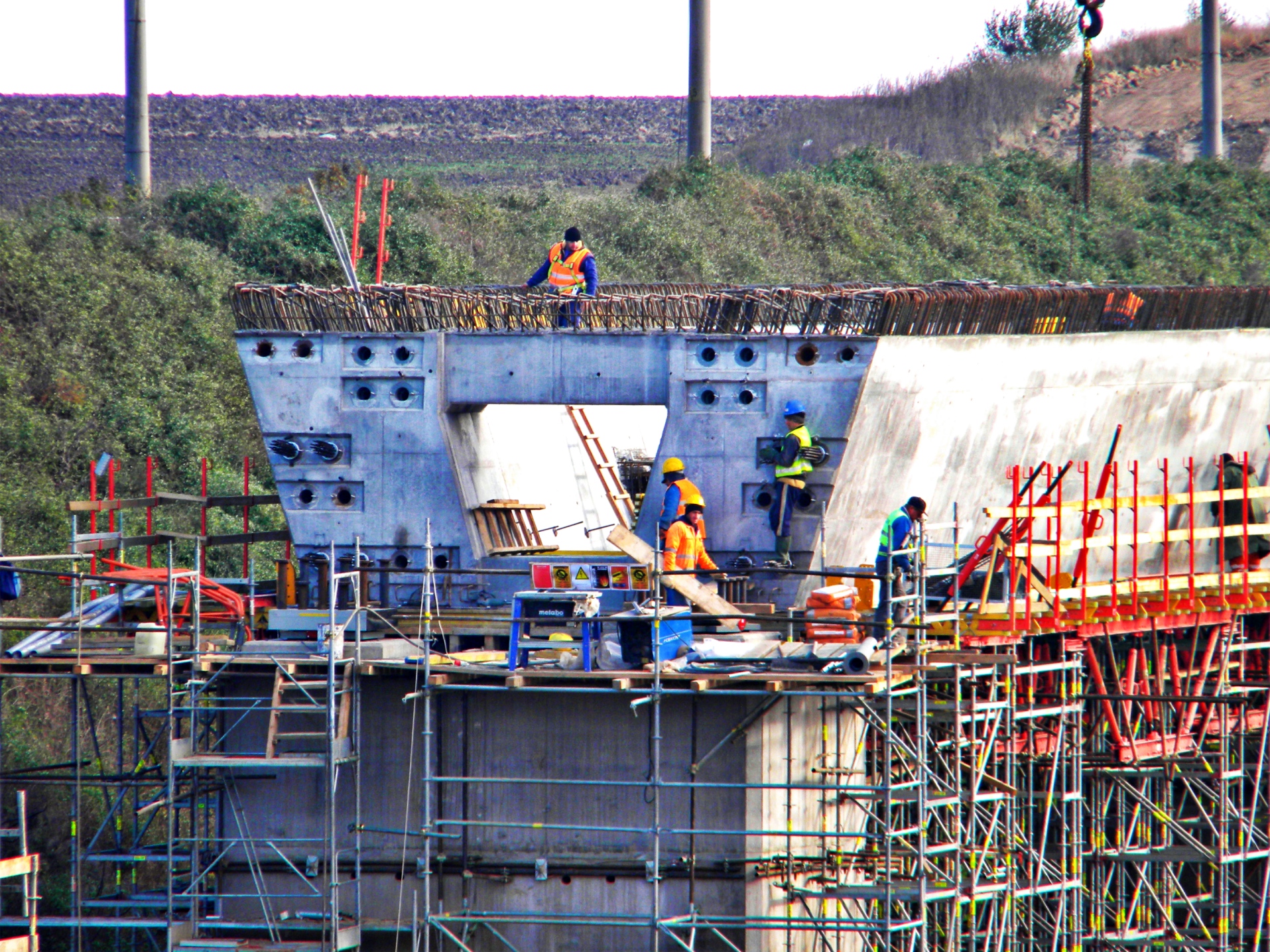
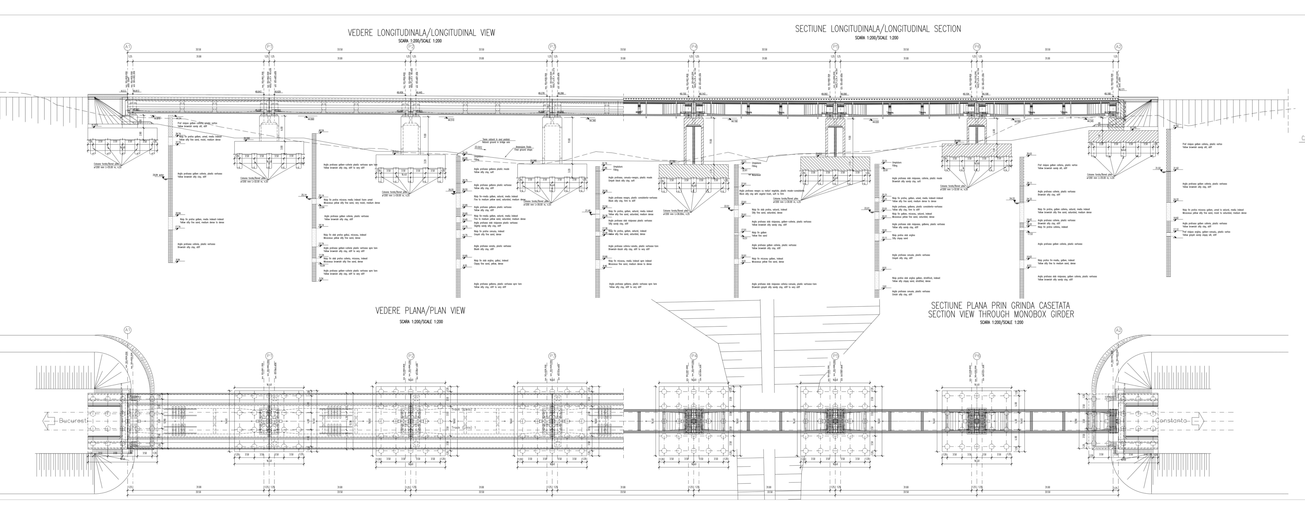
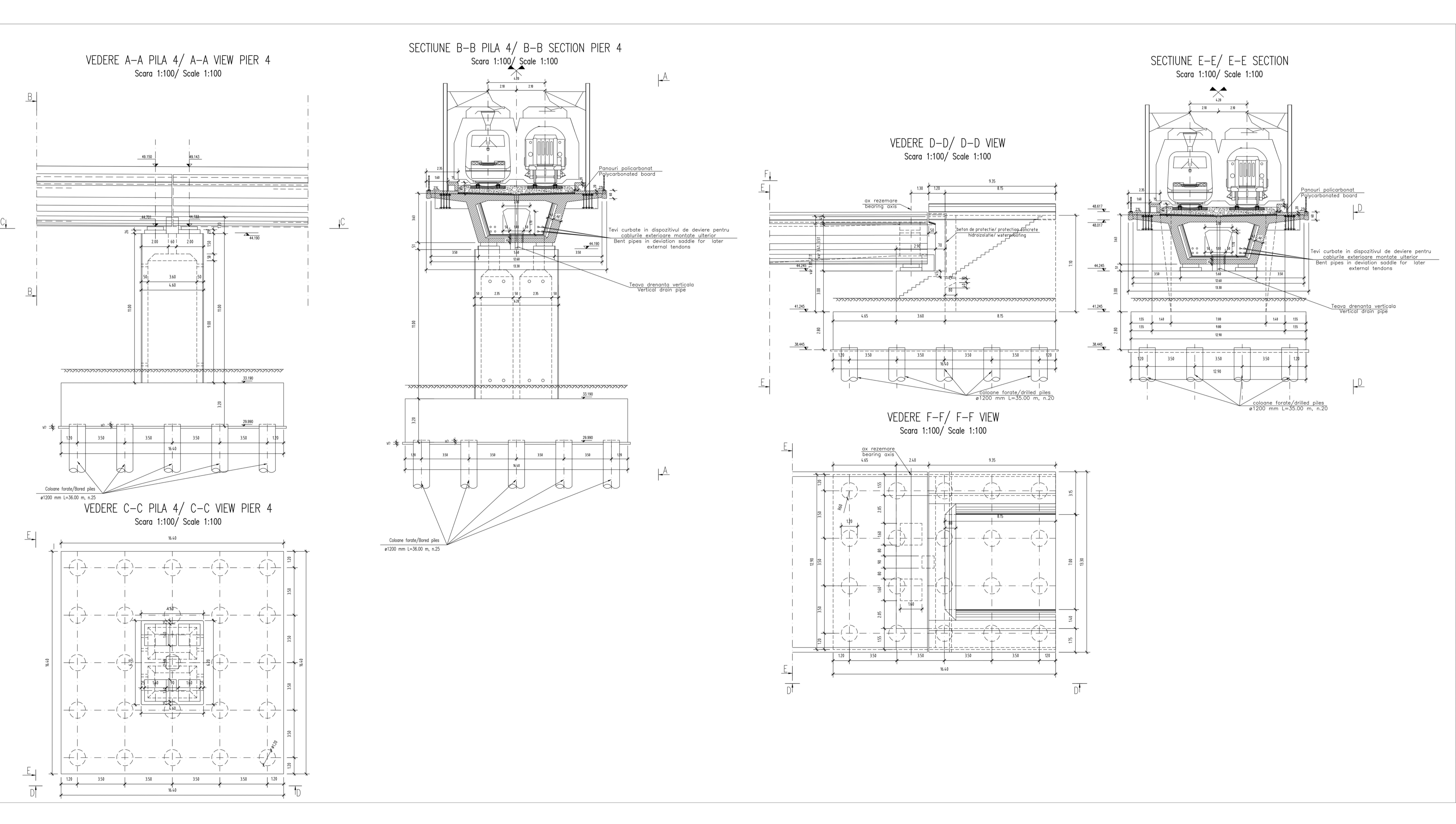
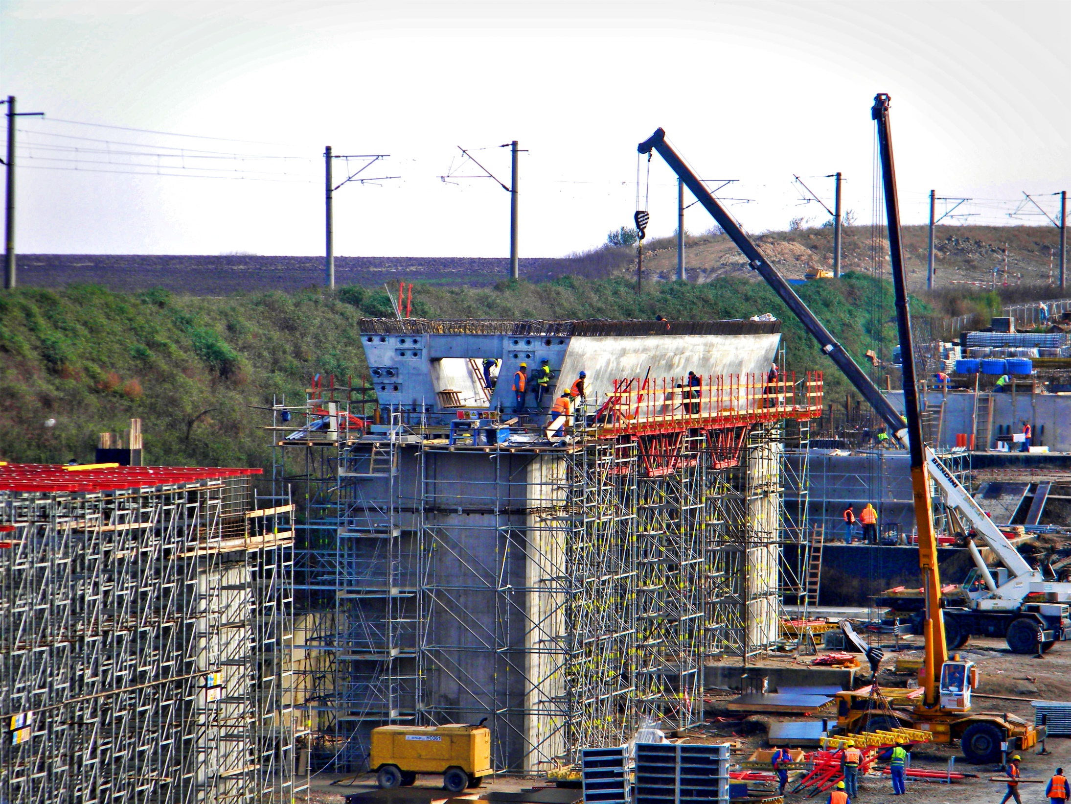
For the project of the new railway bridge km. 55+938 “Sarulesti” of the Bucharest-Constanta line, this report deals with detailed design of bridge prestress concrete deck. The superstructure is characterized by single box girder type with internal post-tensioning. The bridge is made of 7 equal decks, simply supported over 31.0m span length on piers and abutments. Bridge deck is characterized by two railway track lines and two lateral footpath for a total transverse dimension of 12.6m. Bridge deck has constant depth of 3.63m, that means 1/8.5 of span length. Bridge deck is a single-box girdercast in situ and the construction sequence is span-by-span. Deck section is cast in two stages with the bottom slab, webs and diaphragms cast first and the top slab cast soon after. Box girder section is subdivided in five main concrete elements: Bottom slab of constant width 5.6m and thickness variable from minimum of 0.35m, constant for 18.9m at centre span, and maximum of 0.55m near supports; Two inclined (73°) webs of minimum thickness 0.60m, constant for 18.9m at centre span, that increase up to 100cm near supports; Top slab, of constant section and variable thickness from 0.58m at supports and 0.30m at cantilever end; Diaphragm cross wall, positioned transversally on bearing axis with constant thickness of 1.50m and a central opening for access inside the box girder; Intermediate ribs for deviation of external post-tensioning, provided as safety cables. The top slab is protected by waterproofing layer and concrete layers, both on footpath and ballast rails support. Bridge deck is supported by 4 bearings of teflon-steel type, fixed + transverse sliding on one end pier and longitudinal sliding + multidirectional sliding on the other end. The construction sequence for the Bridge deck is in situ single-box girder type, cast span-by-span, where each span is simply supported on 31.0m lengths. Deck section is cast in two stages with the bottom slab, webs and diaphragms cast first and the top slab cast soon after. After setting up the outer formwork, the reinforcement and the prestressing tendon ducts are fixed. The internal formwork for webs and diaphragms is then placed. A short width of shutter is placed along the top of the bottom slab adjacent to the webs to prevent the web concrete from slumping. However it is not necessary to provide shutters over the rest of the bottom slab. A separate internal form is used for the top slab between the webs. With the bottom slab and webs already cast, the top slab shutter is arranged as a “table” from supported on hardened concrete. After the top slab concrete has gained strength, the table form is lowered and moved forward for the next section of deck. The time lapse between casting of webs and the top slab should be kept to a minimum to reduce any potential early thermal and differential shrinkage effects between the two concrete pours. The internal post-tensioning is activated in two different stages: After first stage of section cast (bottom slab, webs and diaphragm): cables WEB2 (anchorage at barycentre of U section) and LOWER 1 and LOWER 2 cables. Minimum concrete compressive strength required is fckj = 30 N/mm2. All cables are prestressed from one end only (because possible interference with consequent decks already built) and up to 100% of total initial prestress at jacking (σpi = 1200 N/mm2). After second stage of section cast (top slab): cables WEB1 (anchorage at barycentre of composite section), WEB3, LOWER 3 and LOWER 4 cables. Minimum concrete compressive strength required is fckj = 30 N/mm2. All cables are prestressed from one end only (because possible interference with consequent decks already built) and up to 100% of total initial prestress at jacking (σpi = 1200 N/mm2). Regarding in fact the infrastructure (foundations, piers and abutments), considering the nature of foundation fields and loads induced by the superstructure, we opted for indirect foundations composed by rectangular blocks, founded on piles. Block dimen ions were obviously determined by the number of piles needed for transpher of loads induced from the superstructure. Anyway, in fact, piers have all similar plane section 6.20mX4.60m with walls 50cm in width, while the height is in fact determined by the designed level, which involves a variability from min. 6.00m for marginal piers, reaching to a max. height of 11.00m for piers disposed in the middle part of the viaduct. Abutments are massive type, founded on blocks and further on piles. Piers, have all similar sections at the base and similar pierheads. Especially the latter, has at his top one acces trap-door which allows inspection from the interior . The pier is composed by an empty section, stiffened by the presence of an central wall along the entire height. Beside the “inspectionability” for pier internal side, taking into account that part of the cables are re-tensionable type, decks are constructed in a way to ensure the space needed to allow the tensioning procedure. In fact, between two succesive decks, we may find a transversal manhole 1.00m long. Earthquake design for the viaduct has been accomplished trough a detailed analyse. Particularly, it was considered that under the extreme seismic load (Ultimate Limit State) it develops ductility in base sections for piers, both in transversal, and longitudinal direction . Regarding global behavior for the deck viaduct under seismic load, considering the chosen linking scheme, which allows representation of the entire as a sequence of simply supported beams, having longitudinal diplacements allowed from a single side of the girder, seismic load developed longitudinal is ridistributed uniformly on different piers, not letting efforts to concentrate over one single area. Regarding construction method, absence of singular conditions along the way, modest height of the piers and la reduced span for decks , have sugested realisations of this simple scheme, represented by a sequence of simple supported beams. The optimization in economic terms and in terms of implementation times was obtained in fact dividing realisation of the deck in two different phases. In fact, firstly it was accomplished the inferior side of the girder using external support structure (scaffolding), while in the second stage the inferior part of the box girder, already realised, was used as a support for the plate. This fact allows reduction of costs for the deck, given that it was possible to use a more slender structure, needed to sustain a lighter weight as against sustaining the entire section (base+plate), and on the other side it allowed improving execution terms reusing the same scaffolding for execution of the next beam, while tensioning procedures and plate casting would proceed for the plate already cast.